
Why does RO-treated water need another UV stage before storage?
The reason is a change in process boundaries, not repeated treatment. Ultrafiltration (UF) and reverse osmosis (RO) perform separation. Once water leaves the membrane system, downstream ion exchange, remineralization, degassing, buffer piping and contact surfaces can change its microbial status again.
One treatment does not permanently fix post-membrane water quality
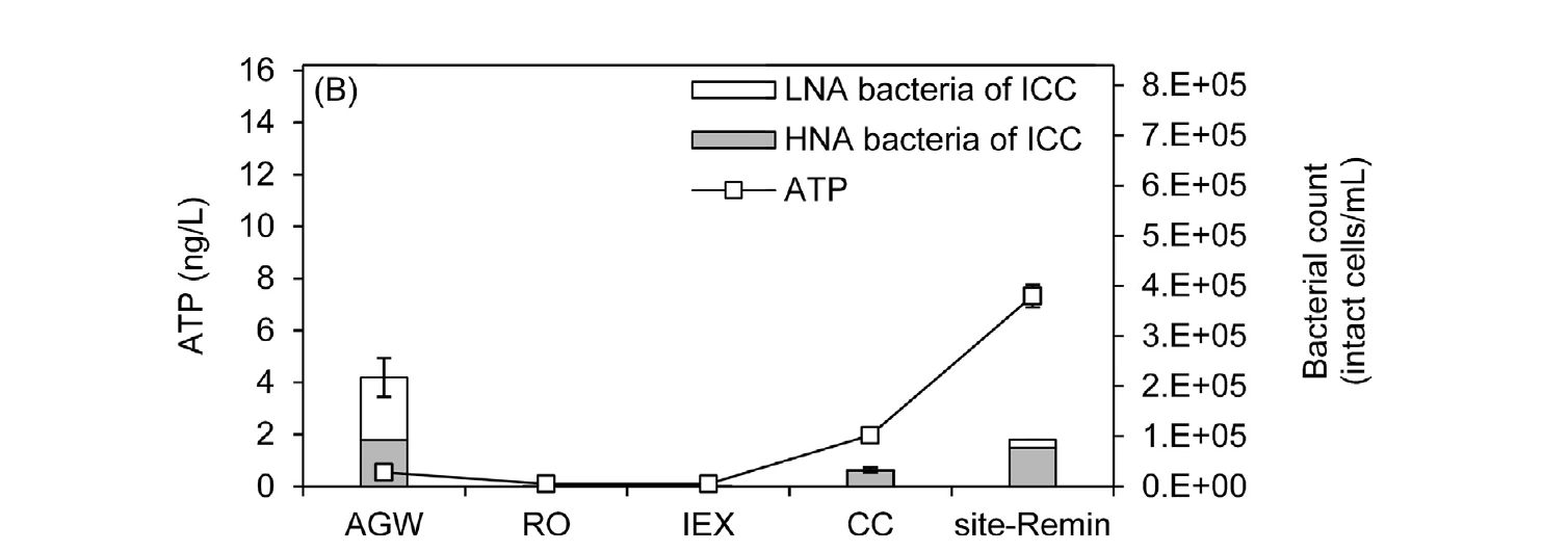
In an RO drinking water system, Sousi et al. observed that RO reduced intact cell counts below detection, with removal exceeding 99.6%. After ion exchange, calcite contact and aeration, intact cell counts and bacterial growth potential rose again.[1] A review of biological stability likewise notes that residence time, temperature, materials and hydraulics can affect subsequent regrowth even when RO greatly reduces cells and nutrients.[2]
Our recommendation: reduce the initial load at the tank inlet
UF / RO | Low-pressure UV | Hygienic storage tank | Low-pressure UV |
Primary recommended position: after all membrane post-treatment, as close to the tank inlet as possible, with a short downstream hygienic pipe section.
Optional additional positions: tank outlet, recirculation loop or before critical blending and filling processes.
Install pre-storage UV after all membrane post-treatment and as close to the tank inlet as possible. It reduces the load of microorganisms capable of reproduction entering storage and makes the handover between membrane and storage systems a control point that can be monitored, alarmed and traced.[3]
This does not provide continuous tank protection. UV leaves no disinfectant residual and cannot treat contamination introduced later through vents, tank walls, maintenance or downstream piping. Hygienic tank design, appropriate turnover, vent filtration, recirculation and clean-in-place (CIP) must be managed separately. Systems with long storage times, complex recirculation or stricter downstream microbial requirements may add low-pressure UV at the tank outlet, in the loop or before blending, filling or other critical steps to reduce organisms reintroduced during storage and transfer. Pre-storage UV lowers the initial incoming load; post-storage UV forms the final barrier before production. The two control points have distinct, complementary roles.
Why low-pressure UV suits clean post-membrane water
Low-pressure and low-pressure high-output mercury lamps emit almost monochromatically at 254 nm. Typical data compiled in the USEPA manual show high germicidal conversion efficiency and long lamp life. Low particle content and high, stable UVT after membranes favor 254 nm UV transmission.[4]
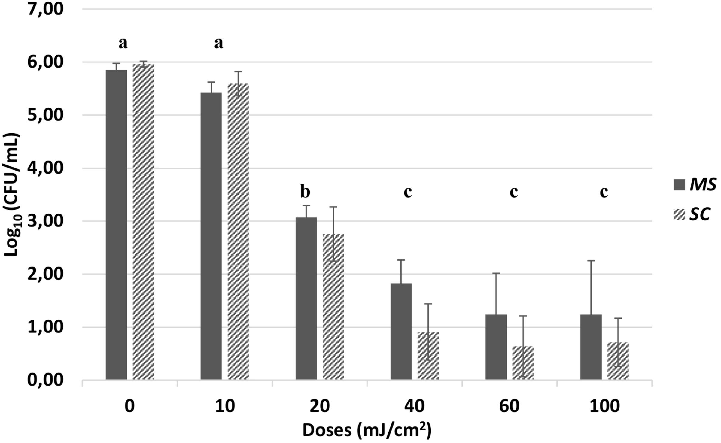
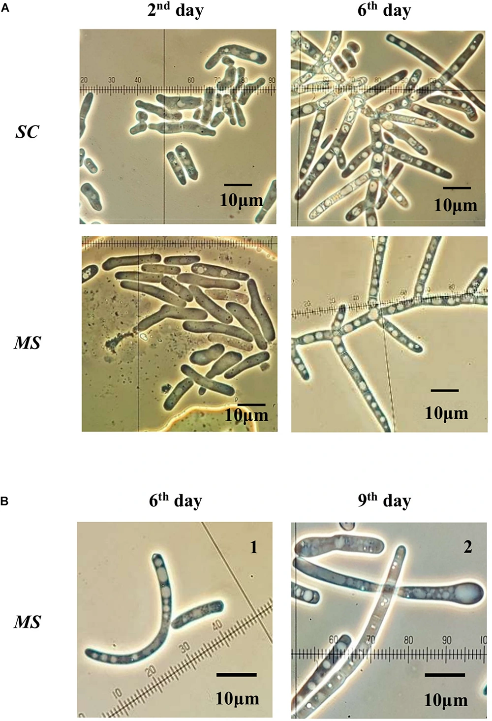
However, “after RO” does not replace measurement. Selection still requires the lowest measured UVT at the installation point, maximum flow, target microorganisms and end-of-lamp-life conditions; high UVT must not be assumed after UF. A common design for RO permeate before storage uses 254 nm and 40 mJ/cm². The cited challenge experiment instead used a 255 nm UV-C LED collimated beam in an SPS cell suspension: 40 mJ/cm² significantly reduced culturable counts of two filamentous yeasts from RO membranes, but not below the 1 CFU/mL detection limit.[5] This illustrates why dose must follow target organisms and reactor validation rather than a universal number.
How WDU-LP addresses these requirements
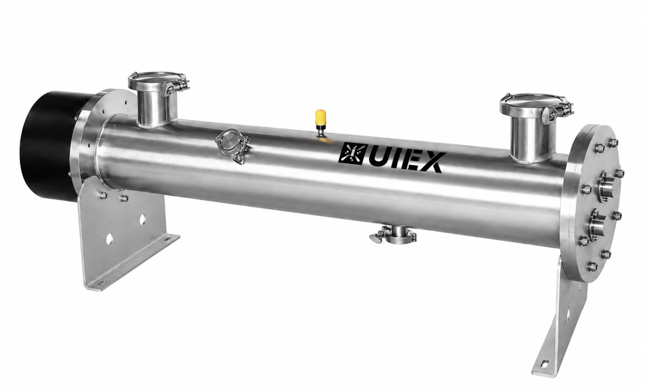
WDU-LP uses low-pressure amalgam lamps in 65–1200W models, with fixed or adjustable power configurations and expected lamp life up to 16,000 hours.
The system maintains the target reduction equivalent dose (RED) at maximum design flow, lowest measured UVT and end of lamp life.
Using real-time flow and online UVT signals, the system continuously adjusts lamp power according to a confirmed dose algorithm to meet target dose while reducing unnecessary full-power operation.
Low-dose conditions can trigger alarms, event logging and tank inlet valve interlocks to prevent water outside the set operating dose from entering storage.
Low-roughness flow paths validated for hydraulics and hygienic design reduce stagnant zones and are compatible with the established CIP process.
Correct control-point placement matters more than broad UV claims
The value of pre-storage UV is not a claim that post-membrane water is now sterile. It further reduces the initial viable load before water enters a space with residence time and leaves process evidence for assessing operating status. Membrane treatment, pre-storage UV and hygienic storage must each fulfill their roles to create a complete, auditable microbial control chain.
References
【1】Codex Alimentarius Commission. (2024). Guidelines for the safe use and reuse of water in food production and processing (CXG 100-2023; adopted 2023, revised 2024). FAO & WHO.
【2】European Hygienic Engineering & Design Group. (2025, December 16). EHEDG Guideline 28: Safe and hygienic treatment, storage and distribution of water in food and beverage factories—New available guideline.
【3】Sousi, M., Liu, G., Salinas-Rodriguez, S. G., et al. (2020). Multi-parametric assessment of biological stability of drinking water produced from groundwater: Reverse osmosis vs. conventional treatment. Water Research, 186, 116317. https://doi.org/10.1016/j.watres.2020.116317
【4】Prest, E. I., Hammes, F., van Loosdrecht, M. C. M., & Vrouwenvelder, J. S. (2016). Biological stability of drinking water: Controlling factors, methods, and challenges. Frontiers in Microbiology, 7, Article 45. https://doi.org/10.3389/fmicb.2016.00045
【5】U.S. Environmental Protection Agency. (2006). Ultraviolet disinfection guidance manual for the Final Long Term 2 Enhanced Surface Water Treatment Rule (EPA 815-R-06-007). Office of Water.
【6】Vitzilaiou, E., Aunsbjerg, S. D., Mahyudin, N. A., & Knøchel, S. (2020). Stress tolerance of yeasts dominating reverse osmosis membranes for whey water treatment. Frontiers in Microbiology, 11, Article 816. https://doi.org/10.3389/fmicb.2020.00816